Revisiting high recovery jigs: its development and continued relevance
Changing economies are causing a higher reliance on metals and minerals obtained through mining processes. Since the mid-1900's we have played an important role in the mining industry, recognising the importance of the right equipment to do the job. That’s why we continuously invest in the development of knowledge and tools for efficient mining.
In this blog series on jigs, globally utilised equipment for mineral processing, we would like to help you understand more about mineral separation using jigs, and how we at IHC Mining can help you with your operation.
Jigs for mining minerals
For more than 500 years jigs have been in use for mineral separation. Georgius Agricola first described the application of jigs in the De re metallica in 1550 (a book cataloguing the state of the art of mining, refining, and smelting metals). These jigs were used in land mining and processing applications. Following the development of steam powered dredging equipment, bucket ladder dredgers for alluvial mining came in use around 1880, which resulted in more focus on the use of separation equipment aboard these dredges. First in the form of sluice boxes, but around 1920 jigs became the preferred method as they presented a better processing efficiency with higher recoveries of the interesting minerals mined. The jigs used were derived from the rectangular shapes as already described by Agricola with well-known names like the Harz jig, Bata jig, Yuba jig and Pan American jig.
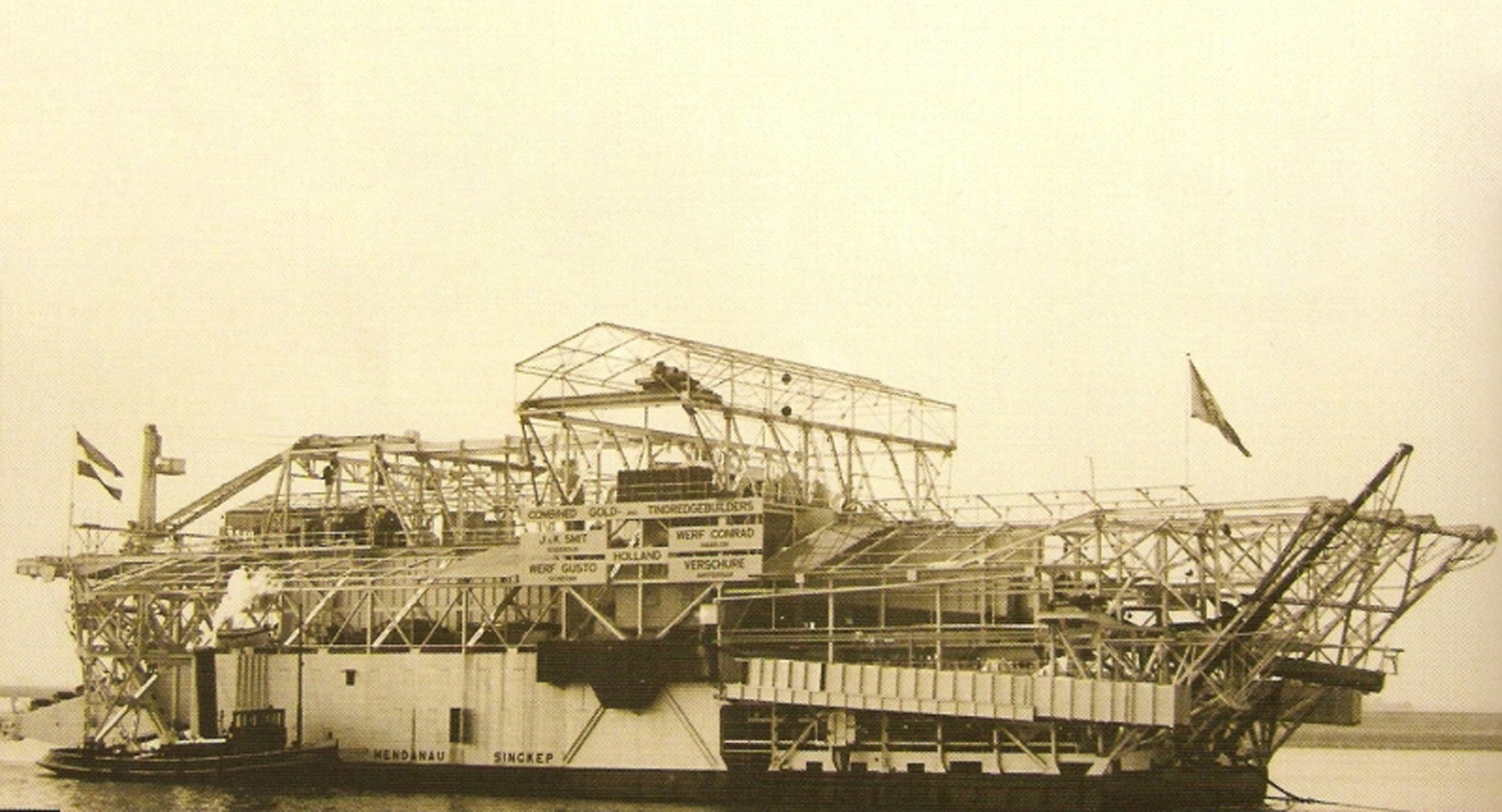
From the beginning of the use of steam engine powered dredging equipment, Royal IHC has been involved in design and construction of mining bucket ladder dredges with integrated separation plants aboard. Growing capacities and more complex operational situations, required more advanced technology. Not only for the dredge mining equipment itself, but also for the separation equipment aboard of these mining dredges.
A lot of innovative technology was developed since the starting point in the late 1880’s for applications in gold, diamond and tin dredge mining. This continued till early 1950 when tin dredge mining requirements required a step forward.
Forced by a growing global demand for tin the operational constraints changed; growing dredging depths, operating off-shore and more efficiency driven demands, forced designer and builders of the equipment to provide answers to these mining challenges. Both for dredge mining equipment and processing. Royal IHC took up the challenge early 1950’s and further developed modern dredge mining equipment as well as high efficient separation methods. A yearlong R&D program at Royal IHC’s MTI Holland (Mineral Technology Institute) followed and resulted in the development of high recovery jigs, which finally resulted in the type we know today.
Designing Royal IHC's high recovery jig
The high recovery jig developed by Royal IHC is a is a so called through screen jig. These type of jigs were primarily developed for the use in alluvial mining projects, with deposits that consist of a sandy matrix material enriched with smaller sized heavier valuable minerals.
Through screen jig principle
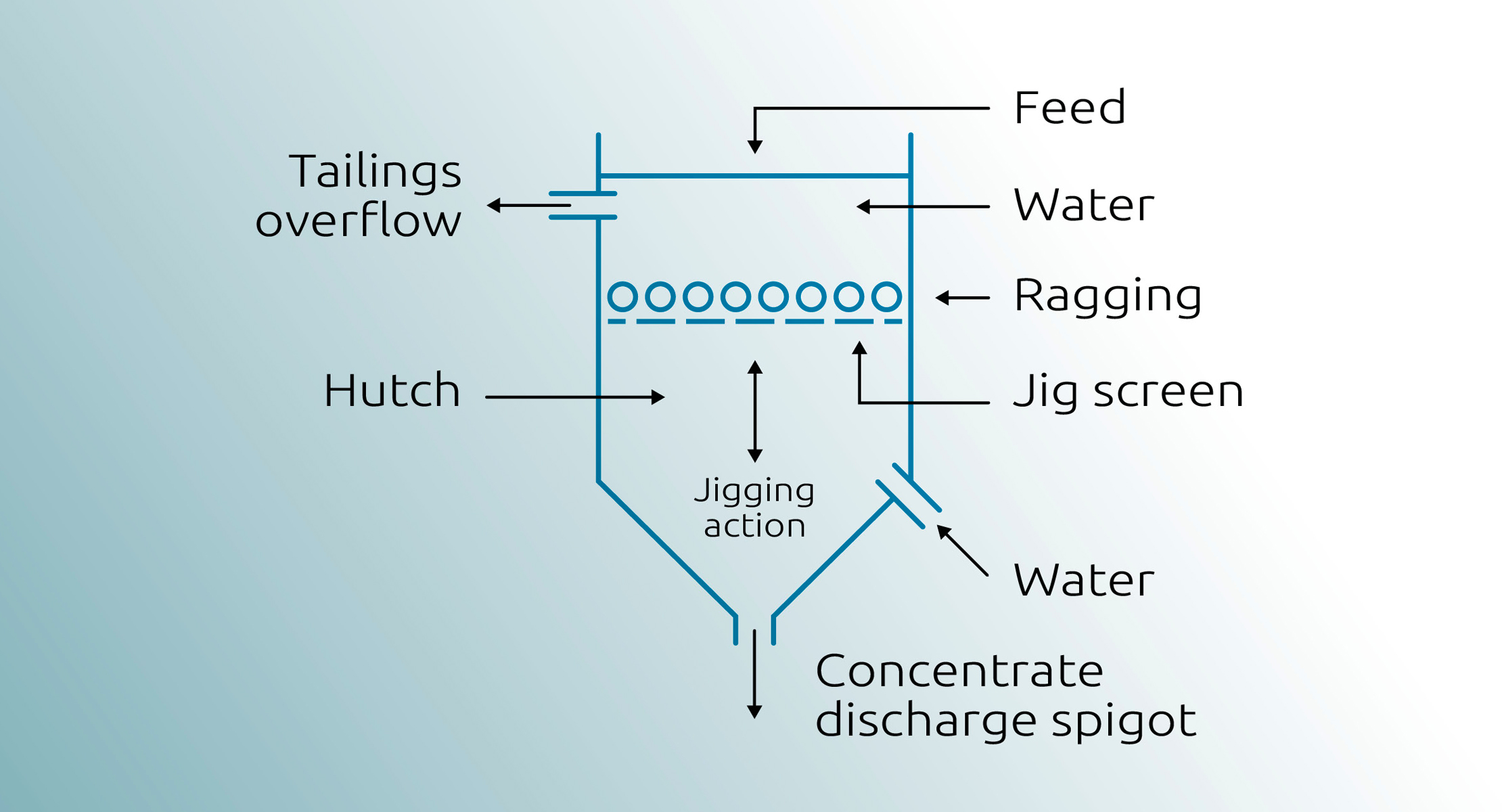
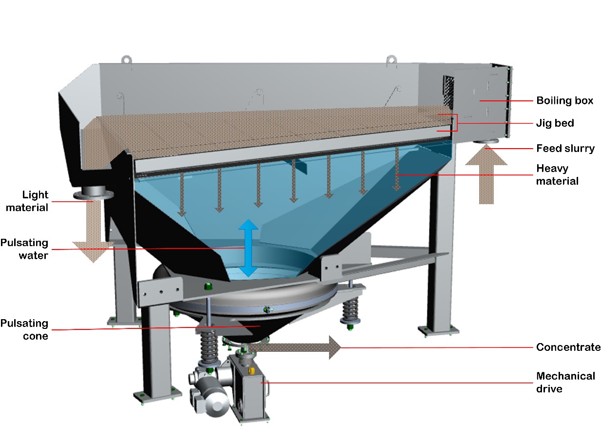
As shown in figure 1, a through screen jig consists of a tank filled with water which is pulsated up and down vertically. A screen installed in the jig holds a filter bed (ragging). Material is fed at the top of the jig together with water, forcing transportation of the feed horizontally over the jig. In this way a sand bed is created on top of the ragging. Due to the pulsation of the water in the tank, the sand bed is fluidised and the heavier mineral particles are gravity concentrated and discharged though the ragging and the screen openings into the hutch below. From here concentrate is discharged through a spigot outlet. The lighter matrix material is discharged as tailings over the tailings weir. In this way gravity separation is affected which results in an enriched concentrate.
Pulsation movements
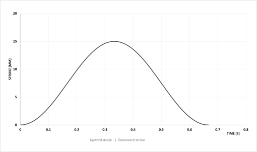
Conventional jigs use a harmonic pulsation movement following a sinusoidal pattern as shown in figure 2. The benefit of hutch water being added to the jig, is that a more efficient pulsation characteristic is created which increases separation efficiency. This additional water opens up the jig bed in the upward movement allowing proper movement of the heavier particles through bed and ragging towards the hutch discharge. However, this also results in an upwards water stream that opposes the transportation of the finer heavier particles through the bed which results in a decreasing recovery of the fines. This is an important negative effect as it causes losses of valuable finer minerals.
Improving pulsation and reducing hutch water
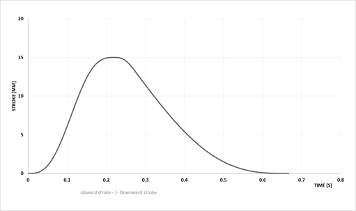
In order to prevent the negative effect of the harmonic pulsation with additional hutch water, an improved pulsation movement was developed based on a lot of testing at the MTI laboratory.
A new, so called saw tooth stroke characteristic, with a fast upwards stroke and a slower downwards stroke (as shown in figure 3), improves the movement of the bed in such a way that less hutch water is required. Omitting the necessity of additional hutch water, this jig drive characteristic results in a higher recovery of the finer heavier particles and so in the recovery of more valuable material.
Changing the shape of things
At the same time of developing this saw tooth drive characteristic, a novel jig shape was developed in the tin mining industry in Malaysia. The rectangular jig design as used so far changed to a circular design. This circular design provided a better distribution of material over the jig bed, less footprint for the integrated mining dredge designs and improved process efficiency. Optimisation of the first circular design applied, resulted in the use of a rotating skimmer to distribute the feed material evenly over the circular jig bed area. This step, as presented by Norman Cleaveland (president of Pacific Tin Consolidated Corporation of New York), improved the operation even more. Combining the circular design with skimmer and the saw tooth stroke resulted in the so-called IHC-Cleaveland jig.
Due to even more changing operational constraints (larger capacities, larger dredge mining depths, higher operational requirements) the size of bucket ladder dredges increased. This resulted in increased feed capacities to the jig plants aboard of the dredgers. It also led to a requirement for the reduction of a high (expensive) area foot print of the jig plants aboard the dredges and an improved feed arrangement of the multiple jigs. The circular shape of the jigs reduced area footprint and allowed for a much better feed distribution to the jigs due to its centralised feed point. Together with the newly developed saw tooth stroke mechanism, a new type of jig was born that could be used efficiently in the modern design of bucket ladder dredges of that time.
Royal IHC's high recovery jigs
Following the development of the Cleaveland jig in the 1950/1960’s, we further improved the drive system and jig design into the even more innovative high recovery system that is used today.
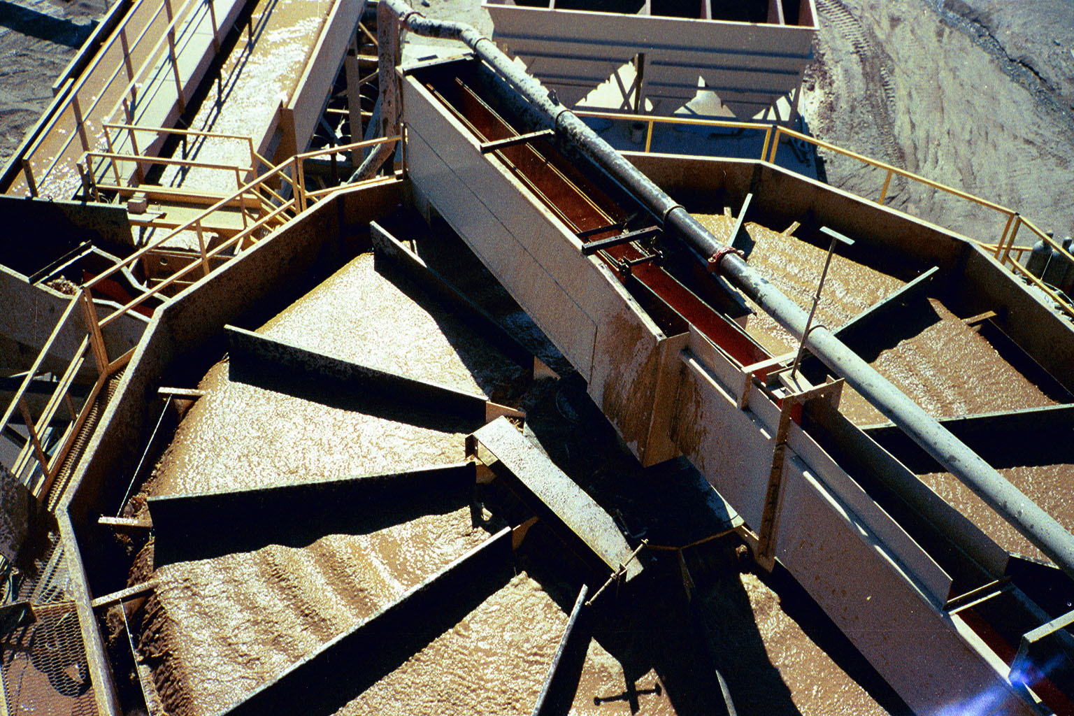
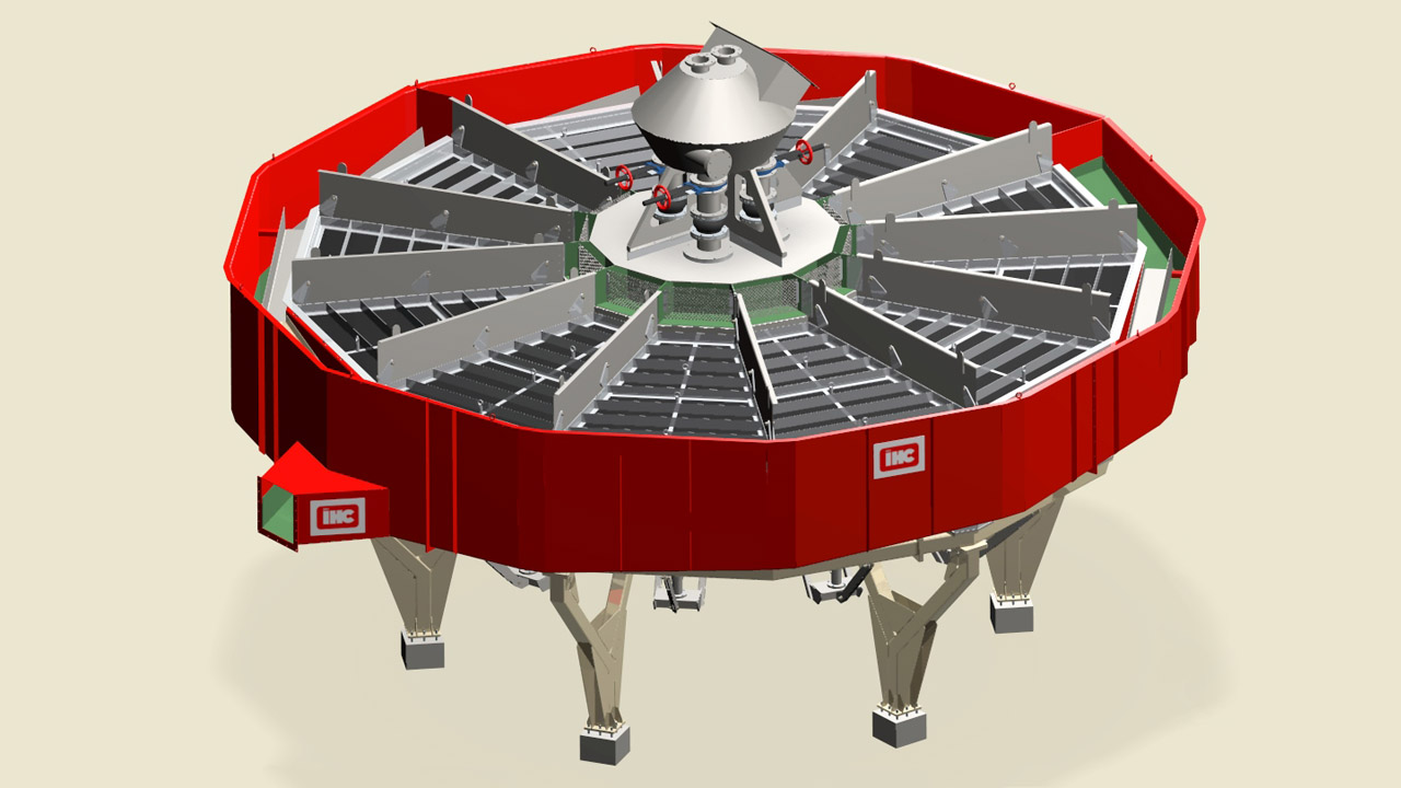
The skimming device as used in the Cleaveland jig was aborted and altered into trapezoidal shaped jig cells with a larger jig length as a trapezoidal shape, allowing a choice to select the number of jig cells based on required feed capacity from 1 to 12 modules. The latter being the full circular jig design. Whatever the number of cells, a central feed intake can be maintained for lesser jig cell arrangements, as can be seen in underneath figure.
Influence of the saw tooth strokes
In addition to the further development of the typical trapezoidal shaped jig we produced, more test work resulted in a better understanding of the influence of the saw tooth pulsation on the jig process.
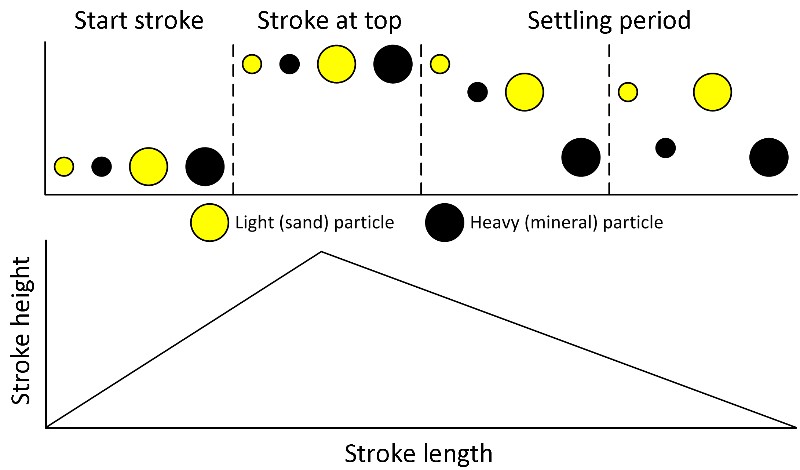
Due to this saw tooth movement, the upward pulsation creates an increased upward velocity of water moving the sand bed vertically as a whole. As explained, less hutch water is required, making an optimum balance between horizontal slurry flow and gravity separation possible. The finer particles will not be swapped away by the horizontal slurry flow. The trapezoidal shape furthermore reduces the slurry velocity towards the tailings overflow, allowing finer sized particles to be concentrated into the sand bed with a higher chance to be recovered.
As less water is used, combined with an expanding trapezoidal shape, the horizontal velocity reduces towards the end of the jig. As a result, it allows concentration of the more difficult finer sized particles even more. This improves the efficiency of the operation as a whole.
Implementing saw tooth strokes
Implementing a saw tooth stroke is not obvious, since it's more complicated than a harmonic drive only (which only needs an eccentric drive). In order to create the saw tooth stroke mechanism, we designed a dedicated camshaft and related drive system. For a single or few jigs the mechanical driven cam box was implemented. For multiple jig modules the pulsators are driven by a mechanical hydraulic drive system, which even results in a lower power consumption.
What's next?
In our next blogs we will further elaborate on the use of high recovery jigs for typical alluvial mining applications, such as tin, gold and other valuable minerals applications. We will also explore other innovative developments surrounding jigs.
Written by
Henk van Muijen